|
20 Sep. 2012
The real symmetric
representation of the Dirac equation.
by Hans
de Vries
|
|
|
|
Download
the PDF
We
describe how one
can transform
the standard
representation
of the Dirac
equation into a
new, spatially
symmetric, real
valued
representation.
It is shown that
this new
representation
can be used as a
direct
replacement in
QED and other
standard model
applications, it
produces the
same results and
the notation is
carefully
chosen to be virtually
identical to the
standard
notation.
|

|
|
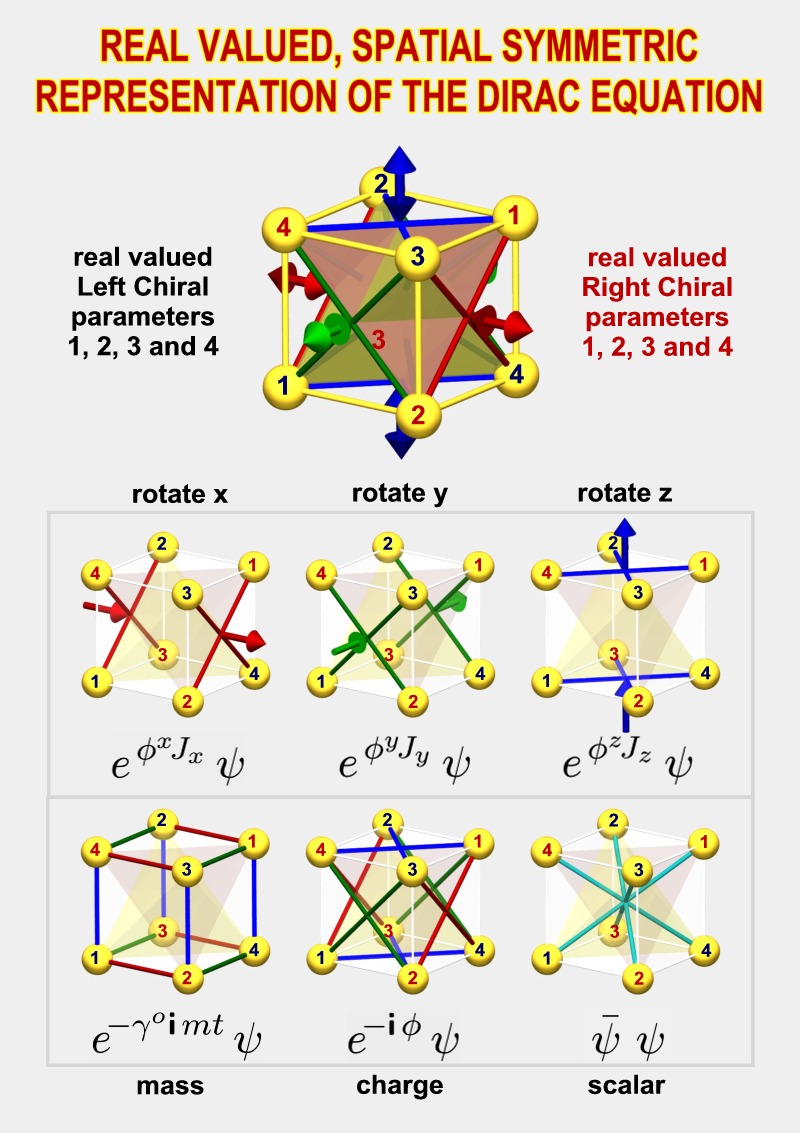
An overview of the
real symmetric representation
|
|
The
spatial symmetry of the 8
field parameters
One major consequence of the
spatial symmetry is that the
8 field parameters get a
spatial symmetric
interpretation as well. The
cube as seen in the
illustrations occurs if we
apply the so called
"current" operator to the
individual field parameters.
Each parameter becomes
associated with a
propagation (current)
from the center of the cube
to one of the 8 vertices.
Each of the 4 central axis
of the cube has two of them,
one is left circular
polarized and the other is
right circular polarized.
|
The eight parameters
together define the
direction of the electron's
current density as well as
the direction of the
electron's spin.
Note that 4
axis-orientations are used
to define directions instead
of the usual 3 spatial
coordinates. This means that
there is a one parameter
redundancy in the
definitions. This redundant
parameter turns out to be
the phase
of the wave function.
It's the phase of the wave
function which enables the
interference of matter
waves. We have found a way
in which nature can define a
phase without needing a
special preferred direction
of rotation.
|

The
720 degrees of spinor
rotation.
One of the most puzzling
statements a student gets to
hear is that
"an electron has
to rotate over 720 degrees
before it returns back
to its original position".
This statement is directly
related to another statement
which says that the electron
is a spin 1/2 particle.
All kinds of strange and
often irrelevant
visualizations are used by
people who are trying to
make sense of this. It turns
out that we can find the
mathematics corresponding to
this spin 1/2 behavior
directly in the
representation itself.
We'll see that a more
appropriate form of the 720
degrees statement is that "the phase
difference is always 1/2
of the geometrical angle"
|
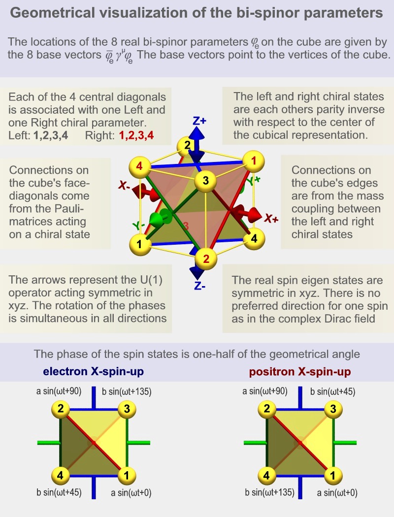
The
electron and positron
eigenstates.
We can calculate the
eigenstates of the electron
(and the positron) directly
from the equation of motion.
The particles oscillate with
a frequency proportional to
their mass. If we look at
the parameters along, for
instance, the x-axis (in
case of a spin in the x
direction) then we see
that there are 45 degrees
phase relations between
parameters that are 90
degrees rotated from each
other.
The images above show 4
parameters with phase shifts
of 0, 45, 90 and 135
degrees. The other 4
parameters (in the positron
case) have phase shifts of
180, 225, 270 and 315
degrees. In the case of the
electron there are extra
signs. This is what
distinguishes the negative
charge from the positive
charge.
|
|
The real symmetric matrices
of the representation
|
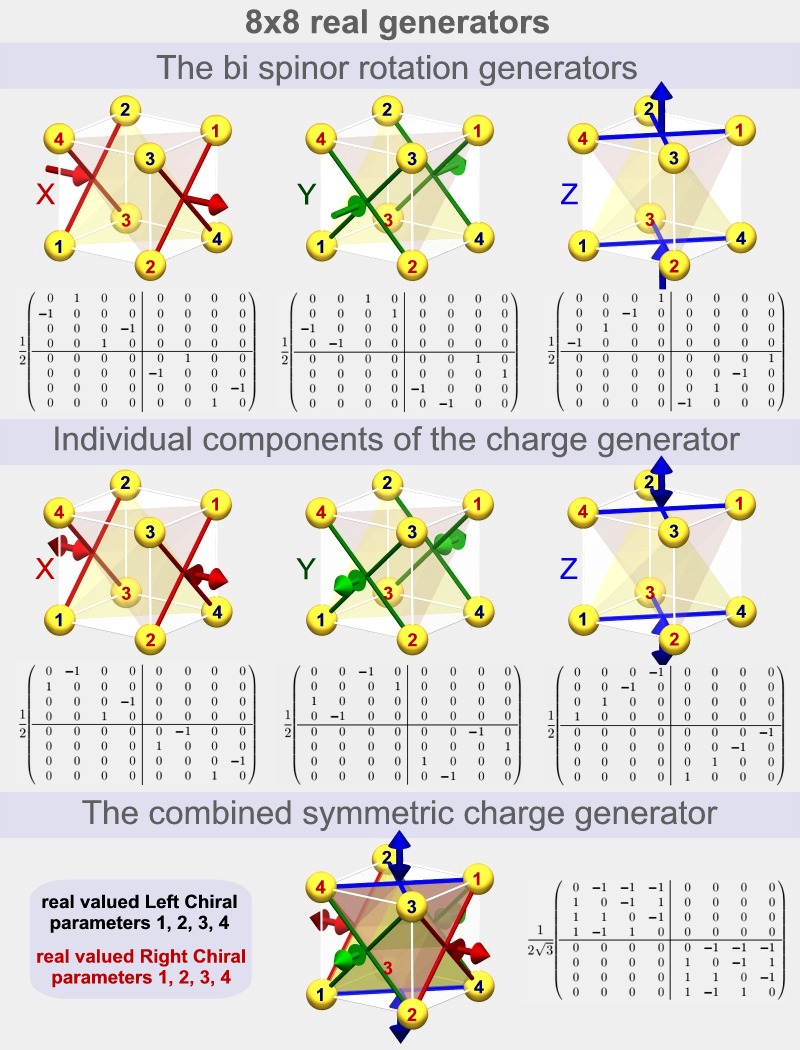
The
rotation generators of spin
1/2 particles.
We can find the
mathematical origin of this
spin 1/2 behavior (or 720
degrees behavior) directly
in the matrices used in the
representation.
We can rotate the current
and spin direction of the
electron field with the use
of the x, y and z-rotation
matrices shown below.
Generally when we perform a
continuous rotation then we
operate on two (orthogonal)
components so that these get
a 90 degrees sine-cosine
relation. The result is then
a circular motion. In the
real, symmetric
representation however we
operate on two parameters
which are not orthogonal (90
degrees) but diagonally
positioned
(180 degrees). The result is
that the phase
difference is 1/2 of the
geometrical angle
as is typical for a spin 1/2
particle
One can see that each
rotation matrix defines four
such connections, each time
between two parameters. This
is why there are four lines
shown in each of the images
(two X's) The signs in the
matrices are so that all
four rotations are defined
as being in the same
direction.
|
The
charge generators of spin 1/2
particles.
If we place the
electron in a potential
field then its phase change
rate will become higher if
the electron's energy
becomes higher and lower
when the energy becomes
lower.
If we rotate an electron
then we will also change the
phase of the parameters (by
1/2 the rate). However if we
give the electron a
different phase change rate
by placing it in a constant
potential field then we
won't rotate the direction
of the spin or the current,
now, what is the difference
mathematically?
We see in the image below
that the individual
components of the charge
generator (which is used to
describe the influence of
the potential field) are
almost identical to the
rotation generators. The
difference is in the
signs. Two of the four
connections are now opposite
in sign. The result is that
the net rotation is zero.
The complete charge
generator shown at the
bottom is symmetric in x, y
and z: The electric
potential field has no
preferred direction in
space. |

HJkh
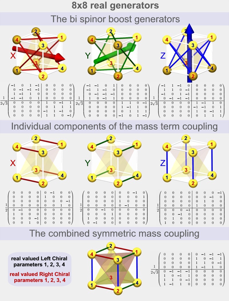
The
boost generators of spin 1/2
particles.
If we boost a particle
then we accelerate the
particle to a different
speed. The matrices used for
this operation are the boost
matrices.
These matrices are somewhat
more complex but from the
images we can see that they
correspond to the x, y and
z-directions.
The most important
difference with the rotation
matrices is that they are
non-zero on the diagonals.
This causes some parameters
to become bigger and bigger
when the boost becomes
larger, while other
parameters become smaller
and smaller.
the +1's found on the
diagonals correspond to the
increasing parameters and
the -1's correspond to
decreasing parameters.
The parameters that become
bigger are drawn with
lighter colors while the
ones that become smaller are
darker. Now, each parameter
corresponds with a current
in its direction, from the
center of the cube outward.
If we boost the electron in
a certain direction then we
indeed expect the currents
in that direction to
increase while the currents
in the opposite direction
should decrease. |
The
mass coupling of the chiral
states.
If we don't place the
electron in a potential
field then we still expect
that its phase changes
continuously and it should
do so with a frequency
proportional to its mass.
The matrix which is
responsible for this is the
"mass coupling" matrix. This
is the matrix which couples
the four left chiral
parameters with the four
right chiral parameters. It
is the only matrix which
does so.
If we compare the 3
individual components of the
mass coupling below with the
3 individual components of the charge
generator above, then we see
that they have the same 4x4
sub matrices
but in different
quadrants.
This means that the mass
coupling has the same effect
as the charge generator when
the four left chiral
parameters are equal to the
four right chiral
parameters, and the opposite
effect if there is a minus
sign between the two chiral
sets. This is the case in
the electron and positron
eigenstates respectively.
The combined mass coupling
matrix is symmetric in x, y
and z.
Mass does not have a
preferred direction in space
just like charge doesn't
have a preferred direction.
|

|
About the PDF
|
The PDF was written
over a period of about 3
years. It contains an
overview in chapter 1 plus a
complete step by step
derivation of the real
symmetric representation
from the standard asymmetric
complex one in chapter 2.
A lot of attention was spend
at the development of the
notation. The final form is
highly compatible with the
standard notation so that
most expressions will be
either the same or almost
identical.The reader will be
able to switch between the
representations without
effort.
|
The real symmetric
representaion is obtained by
going from the standard
complex 2x2 Pauli matrices
to their equivalent 4x4 real
versions. The extra degrees
of freedom obtained make it
possible to make the
representation symmetric.
The consequence of the 4x4
matrices is that SO(4)
becomes the group of unitary
generators of rotation and
charge. The non-Abelian
charges introduced are
discussed in chapter 3.
Further chapters are
under development.
|
|
|
|
|
|
|
|
